The two panoramas would use models composited with painted backgrounds.
I wound up building the three Mars ships, and the Intermountain Railway's version of the ISS. We also photographed a few models I'd built years ago for other projects. I had just under two months to construct and photograph the models.
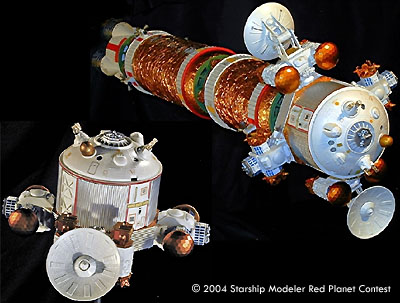
All three of the ships are “generic” Mars ships. Although there are dozens of designs on the drawing boards of NASA, The Mars Society, and others, I was not allowed to pick any one example for the ships. The show was produced in collaboration with the Space Science Institute of Boulder, Colorado, with funding by a grant from the National Science Foundation. If I had used a specific design, it would have appeared that the sponsors were endorsing that design. As a result, I used bits and pieces from a variety of sources, along with input from friends to design the ships. The three ships are, Transfer/Mars Orbiter, Habitat Lander and ERV Lander. It was decided early on to build just one Transfer vehicle, and the two Landers. The Transfer ship is the same for both Landers so it was constructed to allow either one to be mounted on the front.
There are two distinct descent vehicles, one is the Habitat that will form the base of operations and the other carries extra supplies. The second Lander also acts as the launch platform for the ERV (Earth Return Vehicle).
For the update show, it was decided to photograph the models with a digital camera instead of film. It eliminated the step of scanning the slides to get them into digital format. This would make it easier to clean up the images and allow digital compositing for the panorama scenes. Since many of the newer Planetariums are equipped with video projection systems, we could now make the images available in digital form. The images could be printed on color ink jet printers and then photographed on slide film for projection in traditional projectors.
The Transfer ship with the Habitat Lander model is just over 40” long. The ship is broken down into five sections. Starting from the left is the propulsion module. Next are the fuel and oxidizer tanks. The CSM/Command Module follows. The Lander is next and the heat shield/retro pack is at the end.
A truncated engine shroud from the Monogram 1/144 Saturn V houses four shortened SSME 1/72 Monogram Shuttle engines. The fuel and oxidizer tanks started life as Kodak 35mm film reel cores. They were glued together and covered with Space Blanket. The white ribbed cylinders at each end of the tanks are from the old MPC Pilgrim Observer kit. The curved foil covered pieces between the ribbed cylinders and the endplates are also modified Pilgrim parts. The green endplates are modified large Robotix wheels. The green connectors joining the modules are also Robotix parts.
The heat shield was the clear inner hull of the Testors UFO. The backside of the heat shield has a cylindrical, detachable retro pack. The engines on the retro pack are from the 1/200 AMT man in space kit. A 3/8” threaded hollow steel rod runs the length of the model. The rod makes it easy to string the individual sections together in different combinations for filming.
This shot shows the Transfer Ship/Orbiter without a Lander attached. In the foreground is the CSM/Command section. The octagonal section is constructed of sheet stock. The cylindrical section originated as two Pilgrim kit sections with corrugated and strip styrene for additional panel detail. The domed piece is also from the Pilgrim Observer kit. The pivoting communication dishes are from the Millennium Falcon. The sensor pods/airlocks are from assorted building blocks, the sensor domes are buttons and the rest of the details came from the spares box. I used Bare Metal foil for the aluminum panels. Space Blanket, and assorted decals provide additional detail. The silver hexagonal piece in the center of the Command Dome comes off to reveal a threaded socket that allows me to “dock” either of the Landers.
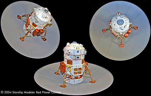
The term Earth Return Vehicle is a bit of a misnomer as the capsule is designed to rendezvous with the Transfer Ship, and then the entire unit returns to Earth orbit. The Lander is made up of three sections. The left Image is a front view. The conical section on the Lander's top is the return ship. The section below the ERV serves two purposes. Its primary function is to be the launch platform for the ERV. The secondary function is storage. Note the four large gold colored cargo modules. The cargo modules are external on this design since the ERV itself extends into the base. The rectangular steel colored objects in the center of each cargo pod are the RCS quads. I found some multi-faceted plastic crystals at the local craft store that looked like they'd be perfect. I used a pin vise and conical Dremel bit to drill nozzle openings in each of the main facets of the crystal. I then made castings for future projects. Below is the actual descent stage. The engine modules are mounted on the sides of the base to allow the maximum use of the interior space.
The middle and right images show the engine modules better. Since this Lander is carrying more supplies, there are three descent engines per side, the Habitat Lander has two per side. The engine frames are constructed from Lego blocks covered with Space Blanket, and J2 engines from the 1/200 Saturn V kits. The great thing about using Space Blanket is that one side is gold and the other silver. This gives you two natural finishes for the price of one. Micro Metal Foil Adhesive was used to attach the Space Blanket material to the model. I brushed a coat of Tamiya Clear Orange over the gold foil. This gives a deep gold color, similar to the Kaptan insulating material used by NASA.
The ERV is a 1/100 scale Apollo capsule grafted to a section of Plastruct cone. I've added separation motors at four points around the ascent capsule. This view also shows the detail and decals around the capsule. The windows are filled with Micro Kristal Klear. Below the capsule are the fuel tanks covered with insulating blanket and the engine bells. The fuel tank section is made from two Heller 1/100 lunar Module bases. The engines are from the old MPC 1/100 Vostok Launcher.
In the center image you can see the docking ring at the top of the ERV Lander. When the ERV Lander is docked to the Transfer ship, there is a cylindrical shroud that mates with the ring on the Lander. There are guide slots in the base of the Lander that help lock the ascent vehicle in place.
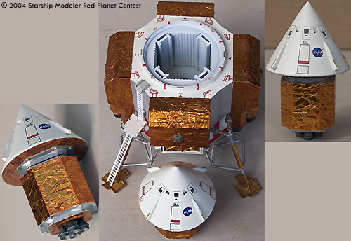
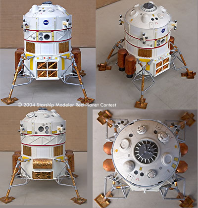
The Habitat Lander module is shown here attached to the heat shield. Between the bottom of the Lander and the heat shield is a cylindrical section that acts as the attachment interface between the Landers and the heat shield.
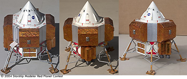
The base of the Habitat Lander, like the ERV Lander, started life as the 1/48 Monogram LEM kit. The landing pads are from the Millennium Falcon. Above the base are two sections, plus the dome, from the Pilgrim Observer kit. I've always liked the Pilgrim kit and have made castings of many of the major parts for use in other projects. I added a large square cargo hatch on the forward face of the base. The hatch is hinged at the bottom to allow it to serve as a ramp. Above the hatch you'll notice a small projection. It represents an extendable cargo arm.
The cylindrical section above the base has three sections from the Pilgrim Observer kit, with added styrene strips for additional panel detail. The RCS quads are from the Monogram 1/32 Apollo kit, note the “No Step” markings on the RCS units.
The domed top has been detailed to keep with the design of the Command section of the Transfer ship. Aluminum foil, Space Blanket, and assorted decals were used for additional detail, along with parts from the spares box. The portholes are filled with Micro Krystal Klear. The Silver octagonal “hatch” seen in the center of the lower right image is removable to allow the unit to dock with the Transfer Ship.
Although you can't see the underside, there are several hatches and a central docking collar used to mate the Lander with the heat shield.
Epilogue
Since the models were constructed with photography in mind, and I was rushed for time, I took a few shortcuts with the design and construction. I'm going to modify the ERV capsule, add some additional details to the CSM Command module, and modify the overall paint scheme.
Image: Three views of ERV Lander
Image: Three views of ERV removed from Lander
Image: Three views of Habitat Lander & Heat Shield
Image: Four views of the Habitat Lander

