Scale: 1/87
This model of an advanced Martian colony was constructed for the Mars Society. The diorama was part of a Mars Society exhibit at the Kennedy Space Center during the summer of 2001. The exhibit included a full size Habitat Lander, the one that is being used as the Mars Desert Research Station. Construction time was 6 weeks. I also traveled to the Kennedy Space Center from Denver to deliver and setup the model.
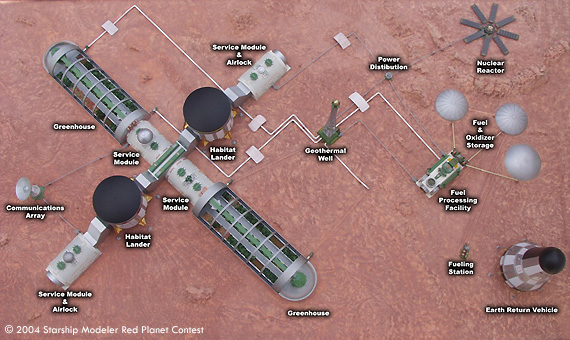
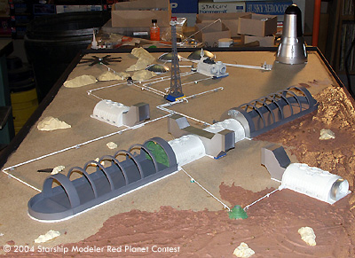
The aerial view above shows the general layout of the base, with labels for the components. The diorama sits on a 5' x 3' base and scales out to about 1:87. There were no formal plans used in building the model. I worked from verbal and written descriptions, a few artist renderings, and my imagination. The buildings can be removed from the ōsurfaceö and stored in a special shipping case. The base has it's own crate for transport. Because of exhibit area restraints, the distance between key elements of the base is compressed. The Geothermal Well, Reactor, Fuel Processing Facility and launch area would be much further away from the main modules than shown.
The core of the colony consists of two cylindrical Habitat Landers that are joined together with a common service corridor. Connected to the opposite side of each Habitat is a Service Module. Each of these modules contains a storage area and airlock section with EVA equipment.
Returning to the central service corridor, we find two more Service Modules. These two modules provide storage and laboratory space. Attached to each of the Service Modules is a Greenhouse that provides food and supplemental air. To support the core, there is also a Geothermal well providing heat, along with a small Nuclear Reactor The Reactor supplies supplemental electricity for the core and powers the well pumps. Both the Reactor and the Well power the Fuel Processing Facility.
The Fuel Processing Facility combines elements from the Martian atmosphere with water and electricity to produce fuel and oxidizer for the ERV(Earth Return Vehicle). The fuel is stored in underground tanks that supply a refueling station near the ERV. The Fuel Processing Facility also provides much of the colonies oxygen supply.
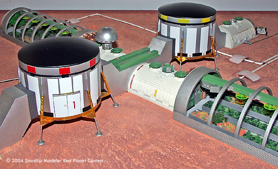
This close up shows some of the interior of the Greenhouses. I've removed the ōglassö from the Greenhouse Modules. You can see the trays of vegetation, Lighting and HVAC ducts running the length of the modules. You'll notice the hatch visible on the Habitat module in the foreground. This is a concession I had to make. Both Habitat modules have two hatches, one on each side of the module. I designed the Service Corridor and the Service Modules to extend from the existing hatches. That would mean that the corridor would hide the hatch visible in the photo. The folks at the Mars Society were afraid that no one would figure out that the Habitat Landers had hatches if you couldn't see them! So I rotated the Habs to make the hatches visible.
The Landers are machined from PVC pipe. A 1/8 inch groove was machined around the upper section of the Landers. Several windows were cut into the bottom of the groove. The tops are the heat shields from the 1:32 Apollo capsule. Landing legs are Plastruct tubes and brass rod with the upper sections covered in gold foil. The feet are Plastruct ōCoolyö lamps. If you look closely, you can see the landing gear is attached to the top of the Lander with separation motors from the 1:144 Saturn V kit. The Service modules started life as Robotix half cylinders with addition detailing. The connecting corridors used Lego's and other assorted building blocks for the core, with corrugated sheet styrene as a covering.
The Greenhouses were constructed of ribs cut from Plastruct tubes attached to rails. Textured sheet styrene was used for the floors and side walls. Plastruct ōIö beams were used for the growing bins filled with plants. Other details came from my parts bins, and things I found around the house. The vegetation and tress are standard railroad offerings. The arched glass was simply thin plastic sheet protectors from an office supply house. The greenhouse was constructed with grooves running the length of the sides that grip the lower edge of the plastic sheet when it's ōdrapedö over the frame.
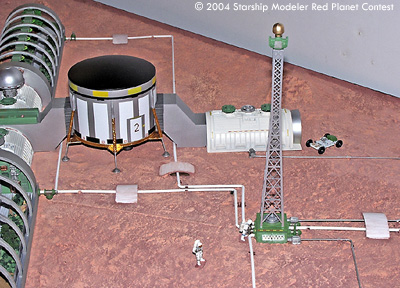
This shot shows the geothermal well, along with the plumbing between the modules. Plastruct pipe and valve provided connections between the modules. The well tower is a converted N gage electrical tower, with a radome added to the top. The little bridges over the pipes are side walls left over from a storage tank kit. The figures are the Airfix ōHOö Astronauts, They give a pretty good idea of the overall size of the modules. The exposed plumbing on the Martian surface was done as a tribute to one of the sponsors of the exhibit, the Steamfitters Union.
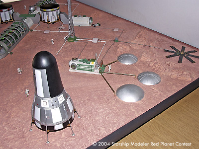
This photo highlights the fuel processing/storage area, reactor and ERV. The Fuel Processing Center is constructed from assorted building blocks and details from the parts box. The intake side, the squared off section with the raised round areas, used 1:35 scale WWII tank wheels to simulate intake fans. The reactor is from a Robotix part with radiator panels from several Revell Armageddon space station kits. The fuel tank storage domes are from several N gauge oil tank kits. The ERV was machined from wood and plastic. Detailing of the ERV is again from castings of old 1:96, 1:100 and 1:144 scale Saturn V parts. Landing legs are the same construct as from the Habitat Landers.
The Martian surface consists of fine grain sand mixed with a slightly diluted solution of carpenter's wood glue. The rocks were castings from off the shelf rubber molds. Tempura paints were used to give the overall red color, and then lighter shades of rust and yellow were dry brushed over the base coat as highlights.
A construction shot. You can see the rock castings and some of the Martian ōsoilö before painting. You can also see the rib construction of the greenhouses better. The front of each greenhouse was removable to make it easier to add the planters and other internal details. The quarter dome for the nose was cut from a Plastruct clear dome. All the modules, figures and plumbing had locator pins that allowed everything to be removed from the base and stored for transport. All the parts were numbered, as were the corresponding mounting points on the base.
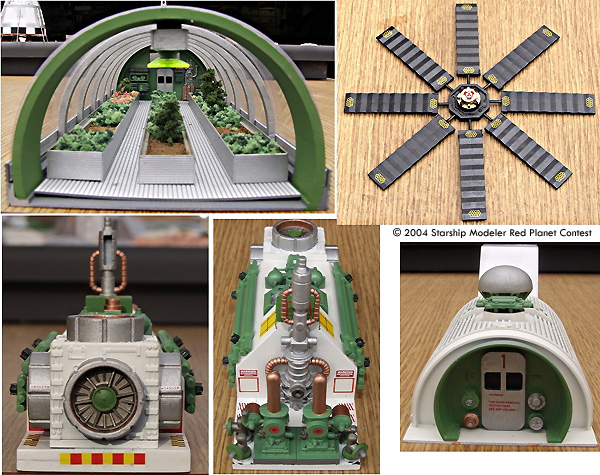
Clockwise from the upper left we see a shot into the greenhouse from front. The domed nose slides into notches at this end. You can see the hatch and other hardware on the far wall. You can see the planter details a bit better here. There are three Plastruct ōIö beams that have corrugated sheet styrene side wall extensions. They were filled with layer of wood glue, and while it was still wet, earth, shrubs and lichen were pressed into the mixture. You can see a thin gap between the bottom of each arch, and the outer wall. The grove is what holds the curved plastic window in place. The HVAC/Power Duct runs along the top of the arch.
Next is a shot of the reactor. Note the ōNo Stepö and ōRadiationö decals.
Bottom left shows one of the four atmosphere intake ports on the Fuel Processing module. The tank road wheel can be clearly seen. Assorted warning and procedure decals cover the module for extra effect.
Next is a shot of the output side of the Fuel Processing Module. You can see several pumps and fittings.
In the lower right is the airlock end of one of the Support Modules that attach to the Habitat Modules. The writing on the hatch reads, ōWarning. For door removal restrictions, see SOP Volume 1.ö The small green detail piece just in front of the dome on top of the module is a carburetor from the old Monogram 1:16 Firebird kit.
I also had some additional help from my wife Carole, and my good friend Tim Kuzniar. They both assisted in the pouring of the Martian surface. Tim's background in Astronomical art, and model making, were a great help in getting the surface coloring just right.
I had a lot of fun designing and building the model. I've taken enough photos of the construction stages, and the modules, that I might someday build one for myself.
